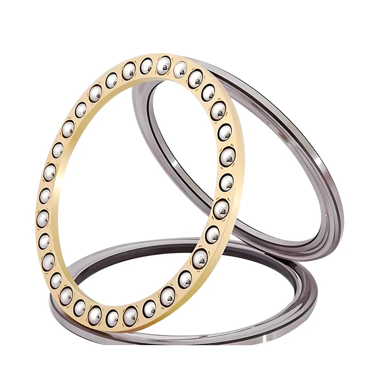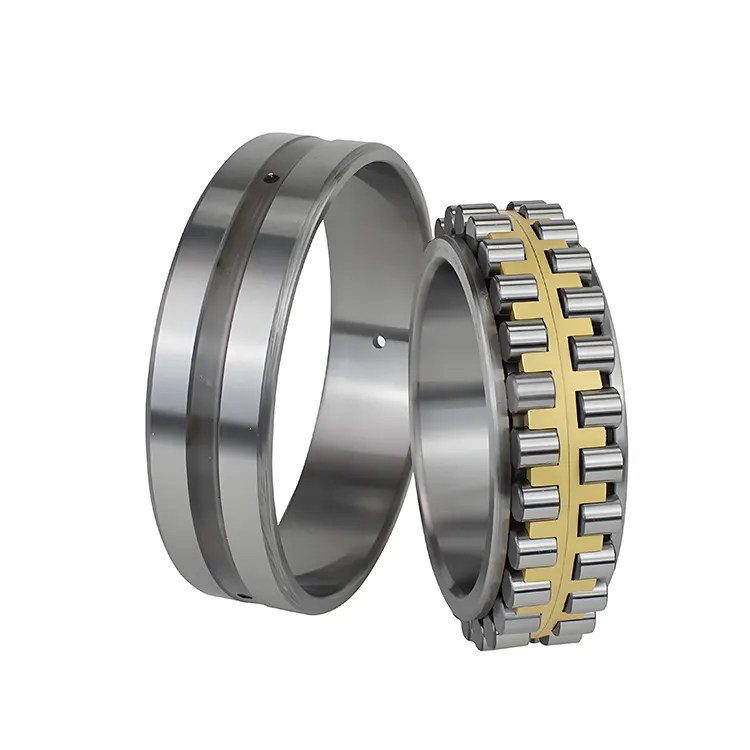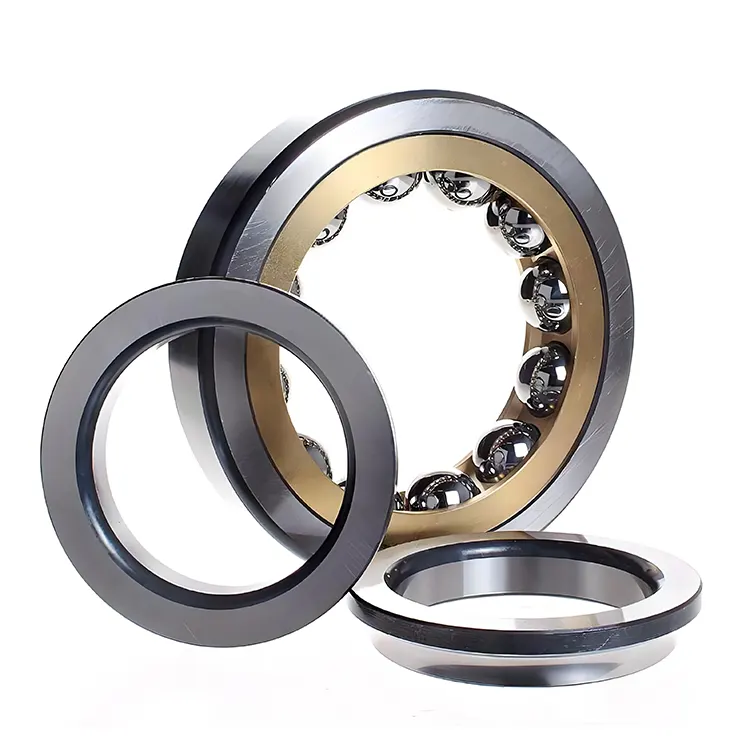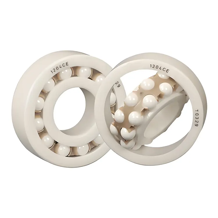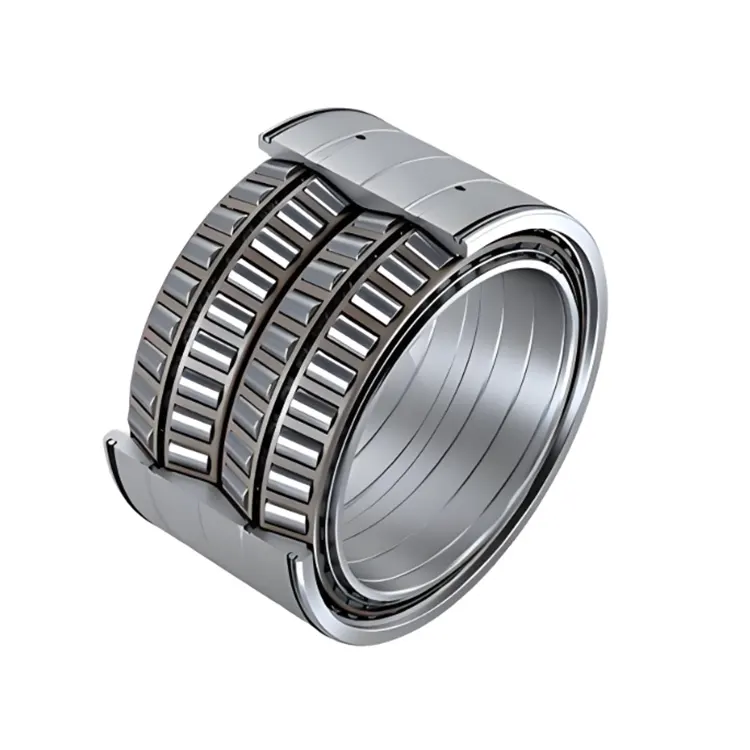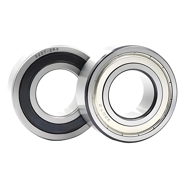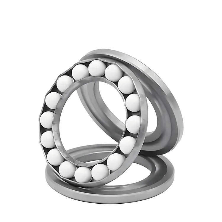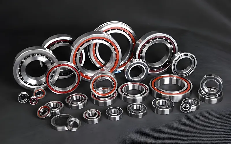


Modern precision machinery, medical devices and robotic equipment face strict limits on internal installation space and overall weight, which puts forward high standards for supporting rotary bearing components. Four Point Contact Thin Section Ball Bearing adopts unique double‑arc raceway geometry and equal thin cross‑section design, enabling single‑row bearing to bear radial, bidirectional axial and overturning moment loads simultaneously. This article systematically sorts structural features, series dimensional classification, material processing standards, multi‑industry matching applications and daily maintenance specifications, focusing on the lightweight and space‑saving strengths that procurement and mechanical designers care about. All content avoids financial evaluation indicators, and only analyzes mechanical performance, environmental adaptability and long‑term stable operation capacity to provide professional selection reference for precision equipment development projects.
- 1. Unique Double‑Arc Raceway Structure & Load‑Bearing Mechanism
- 2. KA/KB/KC/KD/KF/KG Full Series Dimension Standard
- 3. Raw Material & Precision Machining Standards
- 4. Core Mechanical Performance Superiorities
- 5. Typical Precision Equipment Application Fields
- 6. Installation & Long‑Term Maintenance Rules
- 7. Common Technical FAQs For Bearing Selection
- 8. Custom Bearing Matching Technical Service
1. Unique Double‑Arc Raceway Structure & Load‑Bearing Mechanism
Conventional angular contact ball bearings need two matched sets installed back to back to resist bidirectional axial force and overturning torque, which occupies large axial installation space and increases equipment overall weight. Thin section bearings break this limitation through fixed thin cross‑section design, while four‑point contact raceway further upgrades load capacity of single‑row ball structure.
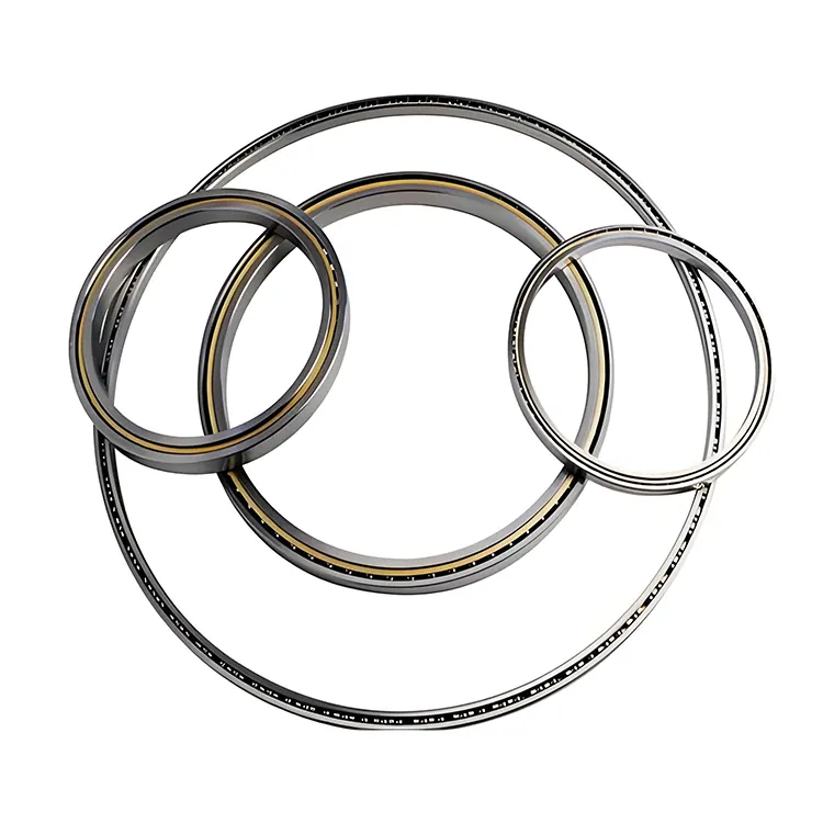
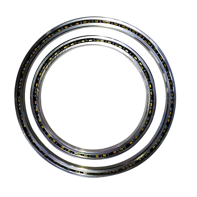
The inner and outer rings of this bearing adopt double intersecting arc groove design, forming four independent contact points between each steel ball and raceway surface. This geometric structure allows one single bearing to replace two paired angular contact bearings, greatly simplifying mechanical frame layout. As standardized equal cross‑section precision parts, Four Point Contact Thin Section Ball Bearing perfectly solve the space shortage problem of compact precision equipment.
1.1 Working Principle Of Four‑Point Contact Geometry
- Double arc raceway produces 35° contact angle on four sides of each ball, evenly dispersing radial, forward and reverse axial loads.
- Single row steel ball structure realizes triple load bearing function without duplex bearing assembly.
- Equal cross‑section specification ensures consistent rigidity and load rating under different bore sizes of same series.
- Continuous thin wall design reduces overall equipment weight without sacrificing structural stiffness.
1.2 Difference With Ordinary Thin Section Bearings
Radial thin section bearings only support single‑direction thrust load, while single angular contact products can only bear unidirectional axial force. The four‑point contact type breaks this bottleneck, and its thin wall thickness (less than 10% of bearing outer diameter) still maintains comprehensive multi‑load performance, which cannot be realized by standard thick‑wall rolling bearings.
2. KA/KB/KC/KD/KF/KG Full Series Dimension Standard
The complete product line is divided into six core series according to cross‑sectional thickness, covering inch specifications from 1 inch to 40 inches bore diameter. Each series keeps fixed cross‑section size regardless of bore change, which unifies structural rigidity for engineers to carry out standardized equipment design. The table below sorts the cross‑section feature of each mainstream series.
| Bearing Series Code | Cross Section Size (Inch) | Main Load Application Scenario |
|---|---|---|
| KAA | 3/16 x 3/16 | Miniature optical detection equipment |
| KA | 1/4 x 1/4 | Light small robot joints |
| KB | 5/16 x 5/16 | General automation rotating parts |
| KC | 3/8 x 3/8 | Medical rotary scanning equipment |
| KD | 1/2 x 1/2 | Medium‑load machine tool turntables |
| KF | 3/4 x 3/4 | Aerospace lightweight components |
| KG | 1 x 1 | Large industrial robot base |
2.1 Series Selection Reference For Designers
- KAA/KA series: Prioritize when equipment has extreme weight and space limits, suitable for miniature optical and inspection instruments.
- KB/KC series: General universal specification, balanced weight and load capacity, most widely used in medical and light automation devices.
- KD/KF/KG series: For large rotating platforms bearing heavy overturning moment, applied to industrial robot base and large scanning frames.
3. Raw Material & Precision Machining Standards
Long service life and stable precision of thin section bearings depend entirely on steel raw material and multi‑step heat treatment plus grinding process. Ordinary bearing steel cannot meet the repeated alternating load demand of precision rotating equipment, so this product adopts high carbon chromium bearing steel as base material.
- High carbon chromium bearing steel raw material, overall quenching and tempering treatment to reach uniform surface hardness.
- Double precision grinding on inner and outer raceway surface to reduce friction coefficient and running vibration.
- High precision steel ball matched, small dimensional tolerance to guarantee smooth rotation without jitter.
- Stamped brass or nylon retainer optional, adapt to low speed oscillating continuous working conditions.
All raceway grinding processes control micro surface roughness, which effectively lowers running noise and avoids precision drift after thousands of hours of continuous operation. For special working environments such as aerospace low temperature, corrosion‑resistant stainless steel material versions can be customized to match special equipment demands.
4. Core Mechanical Performance Superiorities
Compared with conventional bearing combinations, this thin section four‑point contact structure has multiple irreplaceable performance advantages for compact machinery. Every optimization design targets the core demands of lightweight, miniaturization and high precision equipment development.
4.1 Space & Weight Optimization Value
Replacing two back‑to‑back angular contact bearings with single unit can save more than 50% axial installation space, and the thin wall structure greatly reduces the overall rotating component weight. This feature directly reduces the driving load of servo motors and improves the dynamic response speed of robotic joints and scanning equipment.
4.2 Multi‑Directional Load Carrying Capacity
It can bear radial load, forward and reverse axial load and overturning moment at the same time without auxiliary supporting bearing, simplifying the whole mechanical transmission chain and reducing the number of parts assembled on the equipment frame. Four Point Contact Thin Section Ball Bearing can maintain stable rigidity under composite alternating loads generated during equipment reciprocating rotation.
4.3 High Precision & Low Vibration Operation
- Ultra‑small dimensional tolerance after fine grinding ensures rotation runout error controlled within micro level.
- Symmetrical four‑point force balance structure offsets rotating vibration, reducing equipment noise during operation.
- Low friction raceway surface lowers power consumption of driving motor for long‑time continuous running.
5. Typical Precision Equipment Application Fields
The multi‑load thin bearing structure is widely adopted in industries that pursue compact layout and high rotary precision. Different series specifications can be matched according to equipment load size and space limit requirements.
- Industrial Robots: Applied to waist, elbow and wrist joint rotating parts, lightweight design improves movement flexibility and positioning accuracy.
- Medical Imaging Equipment: CT rotary frames and surgical robotic joints require low vibration and stable long‑time rotation precision.
- Aerospace Devices: Satellite payload rotating mechanisms and aircraft lightweight transmission components reduce overall aircraft weight.
- Optical Measuring Instruments: Telescope focusing frame and laser scanning rotary platform guarantee ultra‑precise angle adjustment.
- Precision Machine Tools: Small turntable and tool holder rotating support to maintain machining dimensional consistency.
6. Installation & Long‑Term Maintenance Rules
Correct assembly and regular lubrication maintenance are the key to extend the effective service cycle of thin section bearings. Thin wall structure is more sensitive to improper installation force than standard bearings, so standardized operation steps must be followed during assembly.
6.1 Standard Installation Specifications
- Use uniform press‑fit tool to install inner and outer rings, avoid hammer impact to prevent thin wall deformation.
- Control interference fit tolerance according to load type, excessive tight fit will increase running friction heat.
- Keep assembly environment clean, prevent metal debris from entering raceway and scratching steel ball surface.
- Align bearing center line with rotating shaft to avoid unilateral load caused by skew installation.
6.2 Routine Lubrication & Inspection Standards
Low‑temperature anti‑oxidation grease is recommended for continuous oscillating operation. Regular inspection items include rotation smoothness, abnormal noise and axial clearance change. Once obvious jitter or friction noise appears during equipment operation, the bearing should be disassembled for grease replacement and surface wear inspection in time.
7. Common Technical FAQs For Bearing Selection
Obtain complete series dimension drawings and technical parameter guides from KOMEL BEARING CO., LTD.. Professional engineers provide targeted bearing series matching suggestions for your precision equipment development projects.